PID Control
- Explained -
Hi to everyone,
In this writing, I want to explaint fundementals of PID Control to my readers.
In my opinion, knowing the pid control is very important because it's used quite a lot in industrial process. So, understanding the this control method is necessary for all automation engineer.
Let's begin !
First of all, we have to ask questions that why pid control is important and why we need it ?
Think about your houses. Almost everyone have thermostat on their house and this thermostat control the temperature of their house.
How the termostats control house ? They use basic ON/OFF control method and according the house's temperature they open or close the natural gas. Let's say, you want to 25 centigrade temperature on your house and you house current temperature is 24 centigrade. Then thermostat will open the natural gas. If after that, your house's temperature become to 26 centigrade, then natural gas will been closed. Temperature control continues in this way.
As a result, there will be graphic like the following ;
You can see the fluctution on your output. But we wouldn't like to this fluctution on our process controls. Because process control variables are very sensitive and it's detectived properly by the designers. Also, to not be some quality problems, set value and actual value has to equal each other. If so, if I can't use the ON/OFF control, what will I do ?
Of course, I will refer to PID control.
Let's look at the PID control diagram and see the what components they have ?
As you can see, there are so many different variables call name Kp, Ki or Kd. What stands these words ?
We should understand what they are and why we need them ?
Kp : stands proportional Ki : stands integral Kd : stands derivative
Engineers use these variables due to their requirements. For example, you have an asychronous motor and an encoder and you want to constant speed on your output of motor shaft.
For the constant speed, you are going to take feedback from encoder and your driver will send proper voltages, frequencies and PWM signals to your motor. In this way, you will get the constant speed. Because your motor has some loses, at voltage cables or motor winding and these causes the losing some frequency and voltages.
So, if you use just proportional variables, then you will see the following output signal on your motor ;
As you can see, there is a offset on output.When the only Kp is used, then some fluctuation has been done at start time and finally a bit offset occur on output.
It seems that we need another variables that name is integral.
Integral is important to understanding how much is there error on output signal. Thanks to integral, we can understand the how much error are there in total. So we can close the offset gap on output signal. Graphic will be like following in this way ;
As you can see, there is no offset gap on output, when the integral variable have been used.
OK, now we can look at the derivative variable. What is going to be when P,I and D varibles been used together ?
Firstly, let's look the graphic result ;
When Kp, Ki and Kd variables are used together, the system's instability increase and disruptions are hindersed.
Engineers can prefer to P,PI,PD,PID control methods according the their needs. Generally, PI control method is prefered for Velocity Control Applications and PID control method is prefered for Temperature Control Applicatons.
Secondly, Programming and manuplating the PID !
You should know that you have to use stand-alone a pid controller or pid function blocks of PLC makers for implementing the a pid control system.
PLC makers or Machine Designers can write to PID control block but most of Automation Engineers use these control blocks or stand-alone devices. Because the important thing is to know how control pid systems for automation engineers.
As you can see, there is PID control block on Siemens Tia Portal Interface and there are stand-alone devices that can use at different applications for engineers.
If you want to use a stand-alone device to use PID control method, you have to use a relay or solid state relay. If you pay attention to image, you can see there are PID Temperature Controller, Solid State Relay, Thermocouple and Heater.
Controller take a feedback signal from thermocouple and according the feedback signal temperature controller give the AC Power Supply voltage to heater. For safety precautions there should be a relay or SSR between the controller and AC Power Supply. In this way, overvoltage can't reach the Controller before the relay has been damaged.
How do we program the temperature controller device ? Every PID controller has a user guide for programmers.
To use PID Control Block ;
Every PLC maker as like Siemens or Allen-Bradley has a PID control block on their programming interface. These PID control blocks makes designers job easier. Because creating PID control block from scratch is really hard. So we choose ready blocks to use this method.
Let's look at the image together ;
In this block, there is PV input to see Present Temperature Value. Also there are Max and Min Present Value input signals, Max and Min Setpoint input signals. There are P, I and D variables inputs and there Auto or Manuel work modes too. All of these are enough for engineers or designers.
And off course there is output signal to connect with heater in this application that control the temperature on a side of machine.
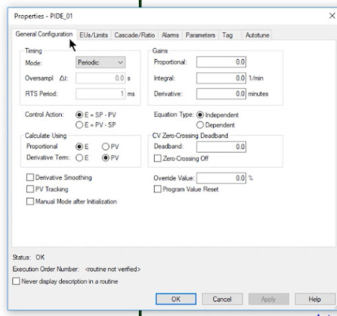
Finally, these control blocks have a configuration tab to determine the P gain value or I,D integral, derivative times.
I hope this writing was usefull for you. I would like to keep write about this topic next days. Please stay tuned and good work to everyone.
Have a nice day.


Yorumlar
Yorum Gönder